Project Description: To build and assemble a TPI and DAF System for Lube Oil Blending Plant in Phillipine
Product Used in this Project:

Watterson Technology Sdn Bhd
Specialized in Water & Wastewater Treatment System
Okada Technology Sdn Bhd
Specialized in Sludge Dryer System
Wastewater Treatment Plant for a Vape Liquid Plant
Project Description: To construct a Wastewater Treatment Plant for a Vape Liquid Plant in Shah Alam, Selangor
Product Used in this Project:

In this Project, Watterson has been entrusted to design and build a wastewater treatment plant to treat Production Process Wastewater to comply with DOE Standard A discharge limit. The WWTP was design as per influent parameter as listed in Table 1:Column 2 and is to comply with the guaranteed treated effluent quality as listed in Table 1: Column 3 (DOE Standard A)
The first part of the WWTP system is the Chemical Treatment System, while the second part of it is a Biological Treatment System. The second part of the treatment is consists of both attached growth and suspended growth biological system. Each part of the treatment system consists of tank/system as listed under Figure 1 below:

Table 1: Comparison of Influent Parameter and DOE Standard A
Chemical Treatment Process

In the Chemical Treatment Process, Watterson had design a system whereby the wastewater will first go through a Tilted Plate Interceptor before entering a Chemical Treatment System and a Dissolved Air Floatation (DAF) before entering the Biological Treatment System.
Equalization Tank
As the characteristic of this wastewater contains high amounts of Free Oil, we have installed a submersible mixer into the equalization tank in order to ensure that the Free Oil is properly mixed and carried into the treatment process. Without the submersible mixer, the Free oil will be accumulated in the Equalization Tank which will consume the volume of the Equalization Tank and create unnecessary Operational Cost in having a third party to remove the accumulated Free Oil.


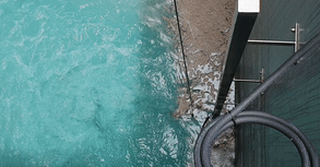
Tilted Plate Interceptor (TPI)

At this stage, the wastewater is passed through to an Acidification Tank where the pH of the wastewater is lower down to pH 2-3 in order for the Emulsified Oil to become Free Oil. This will help in removing all the Oil and Grease which is contain in the wastewater. The wastewater is then channeled into the Tilted Plate Interceptor (TPI). The difference between Watterson's TPI compared to other corrugated plate interceptor (CPI) or Tilted Plate Interceptor (TPI) lies of the mechanism in removing the floating Free Oil. While other CPI or TPI uses a slotted pipe mechanism which is set at an angle and depends on gravity flow, Watterson's TPI uses a skimmer mechanism. This enhances the capability of the TPI to remove oil while removing the need for to continuously adjust the outflow in order to remove the floating Free Oil
Chemical Reaction Tanks


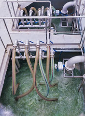
After going through the Oil Removal Process at the TPI, the wastewater will then flow through the chemical reaction tanks. At this stage, Coagulation is first dosed in to remove any contaminants and non-degradable COD before entering a pH adjustment tank where the pH is adjustment back to neutral. The wastewater is then flowed into a Flocculation Tank where Anionic Polymer is dosed to enable the flocs become larger and assist in the sludge removal process in the Dissolved Air Floatation (DAF) System.
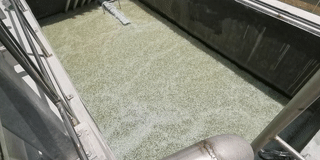
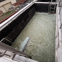
Dissolved Air Floatation (DAF) System

After the chemical treatment process, the wastewater is then flow through a Dissolved Air Floatation (DAF). This system function as the opposite of a conventional clarifier. As the wastewater contain Oil & Grease, DAF is more suitable to be implemented as the sludge will float on the surface due to the Oil & Grease content. By using DAF, it eliminates the floating sludge issue as conventional clarifier relies on the sludge sinking to the bottom therefore issues such as carry forward of Suspended Solids into the Biological Treatment system.
Biological Treatment Process

From the Dissolved Air Floatation System in the Chemical Treatment Process, the treated wastewater is then channeled into the Biological Treatment Process. From here, the wastewater flows through the Moving Bed Bio Reactor (MBBR) Tank. Aeration Tank, Membrane Bio-Reactor (MBR) Tank, and finally to a polishing system which consists of 2 Activated Carbon Filters before discharge into the public drainage system.
Moving Bed Bio-Reactor (MBBR)

The implementation of Moving Bed Bio-Reactor (MBBR) in this plant is to reduce the footprint of the plant due to space constraint. By doing so, the plant size is significantly reduce and is capable of replacing 2 units of Aeration Tank into a single unit MBBR Tank which cuts approximately 30% of the required size of the plant. The reduction of COD and BOD in the MBBR Tank is also more efficient compared to multiple units of Aeration Tank as the surface area for the bacteria to grow is greatly increase by the MBBR media itself. The MBBR alone is capable of removing up to 60% of COD from the residue of the Chemical Treatment Process.
Membrane Bio Reactor (MBR)


In order to consistently meet Malaysia's DOE Standard A discharge quality, the usage of Membrane Bio Reactor is implemented into this plant. By using MBR system, the COD level in the wastewater can be brought down to below 80ppm as per the discharge quality. It also significantly reduce the footprint of the plant as there is no need for a Biological Clarifier and also a huge aeration tank to bring down the COD level. There is also the saving in OPEX in terms of electricity cost as it reduces the energy required to operate a huge blower for a huge aeration tank. As MBR system can withstand a high amount of MLSS, the biological sludge disposal cost can also be reduce as compared to conventional aeration system where the biological sludge required to be control at a lower volume, thus increasing the de-sludging and dispose of biological sludge.
For this plant, we have designed it to run on two (2) train. This enable the plant to continuously run at lower capacity should one of the train required to be serviced. Due to the nature of the wastewater which contain high oil & grease, we have installed Sumitomo's Poreflon MBR technology whereby it can withstand harsh/strong chemical cleaning should the oil&grease in the wastewater foul up the membrane.
Sludge De-watering Process

In this process, sludge generated from the chemical treatment and biological sludge is channeled into a sludge holding tank where the sludge is then pump into a screw press de-watering machine before entering into the OKADA Sludge Dryer for further weight reduction.
Screw Press
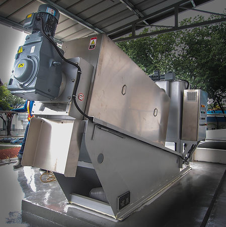

The screw press whilst being compact, it is able to remove up to 25% moisture from the sludge. The permeate is then chanelled to the Equalization tank. The advantages of using a screw press is that it is fully automated and can run continuously without any supervision. Besides that, it does not need any manpower to de-sludge the screw press and very little maintenance is required. The screw press also comes with a sludge conditioning tank which in return saves space and cost of having to construct or fabricate a sludge conditioning tank.
OKADA Sludge Dryer

The OKADA Sludge Dryer helps reduce the weight of the sludge by minimum 50% whereby it uses refrigerant heat pump to dry up the sludge. For this unit, it is design to run continuously without any manpower operating or supervising it just like the screw press. This fully automated system helps reduce in OPEX cost besides than the sludge disposal cost.
Others

The Activated Carbon Filter or ACF is placed as a polishing system and to remove the colour issue faced in the wastewater.
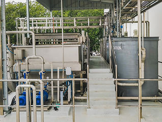
Chemical Treatment Area
DAF System (Left) Chemical Treatment Tanks (Right)
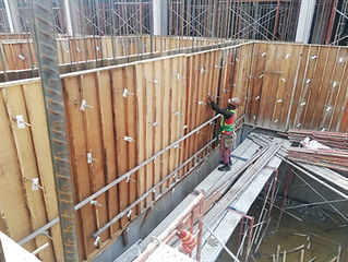
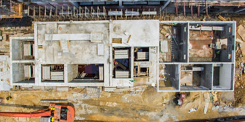
Pictures of the plant under construction